From late 2020 to mid 2021, this 8-bit computer was my first introduction to computer architecture and digital logic. I was initially inspired by Ben Eater's model, but here I've outlined several of the improvements and changes I've made to extend the architecture. I presented this project at the 2021 Greater Vancouver Science Fair, receiving Senior Bronze Divisional.
Keywords
- Soldering, circuit, and PCB design
- Prototyping, troubleshooting, and verification (oscilloscope, multimeter, etc.)
- Microprocessor architecture
- FPGA testing
1. Baseline
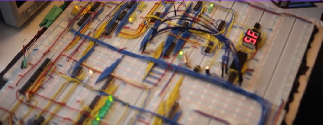
The baseline computer is derived from Ben Eater's model. The first version was made on an array of breadboards, which I later soldered onto circuit boards.
Alongside the logic itself, I also had to make an auxiliary EEPROM programmer to implement the control logic. It's not as sophisticated as Ben Eater's shift register programmer, but it gets the job done.
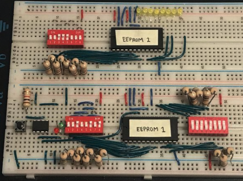
One regret I had in this stage was not using an FPGA or similar large IO device for the control logic. Debugging, writing, and reading EEPROM contents became increasingly challenging down the line, which ended up being one of the largest hurdles in this project.
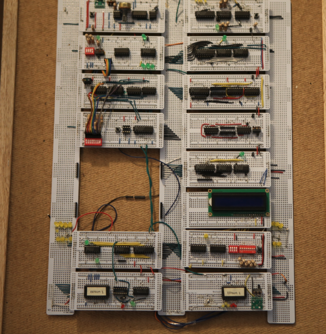
My final build replaced the breadboards with perf-boards and chip sockets, soldering the components on for stability.
2. Conditional programs
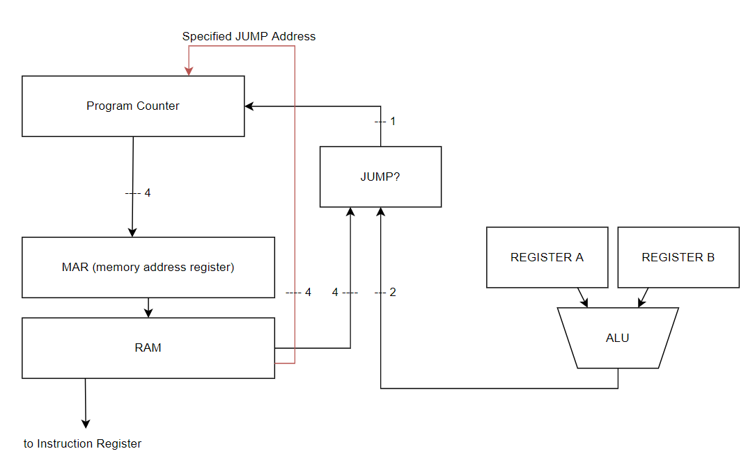
Implementing conditional execution was my largest improvement and what I presented at the Greater Vancouver Science Fair. Instead of a standalone module like RAM or registers, this device synthesizes the RAM, ALU, and program counter together.
Introducing jumps
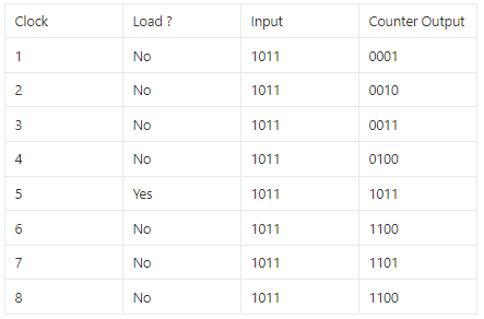
The program counter (PC) is simply a binary counter. When it increments, it sends its count to the RAM, and the RAM returns what instruction should be next executed. Just how registers can load a value by toggling a control pin low, the PC can interrupt its counting, skip to a specified value on its inputs, and then resume counting.
So our program counter has jumped to a specified value. In a sequential program, jumps hold little value since each operation is intended to follow the previous. But for conditional programs, they are essential.
print("starting")
x = 4
y = 3
z = x + y
print("done")x = 4
y = 3
z = 9
if x+y < z:
print("in range")
print(z)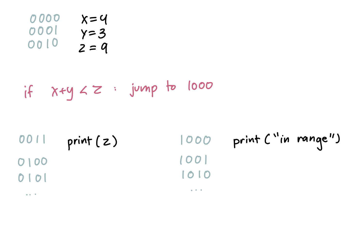
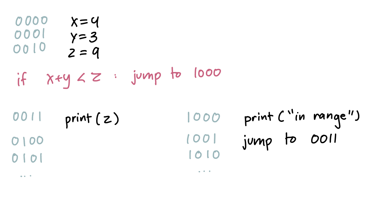
Since x+y is indeed less than z, our CPU is told to jump to memory address 1000 to execute "in range". But we also need to jump back afterward, since print(z) should execute regardless of the condition.
Implementing jumps
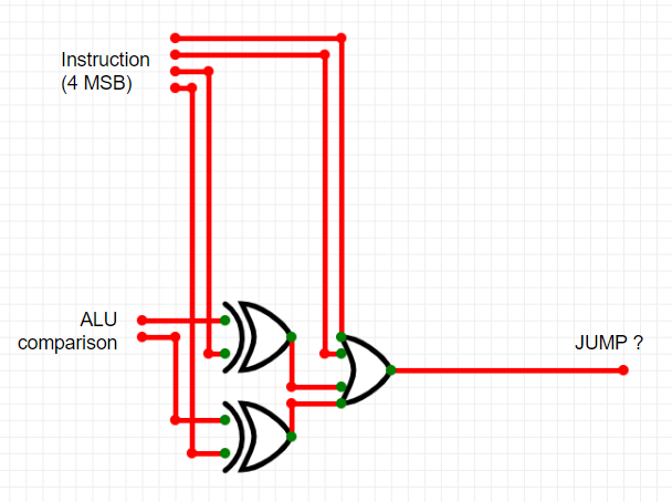
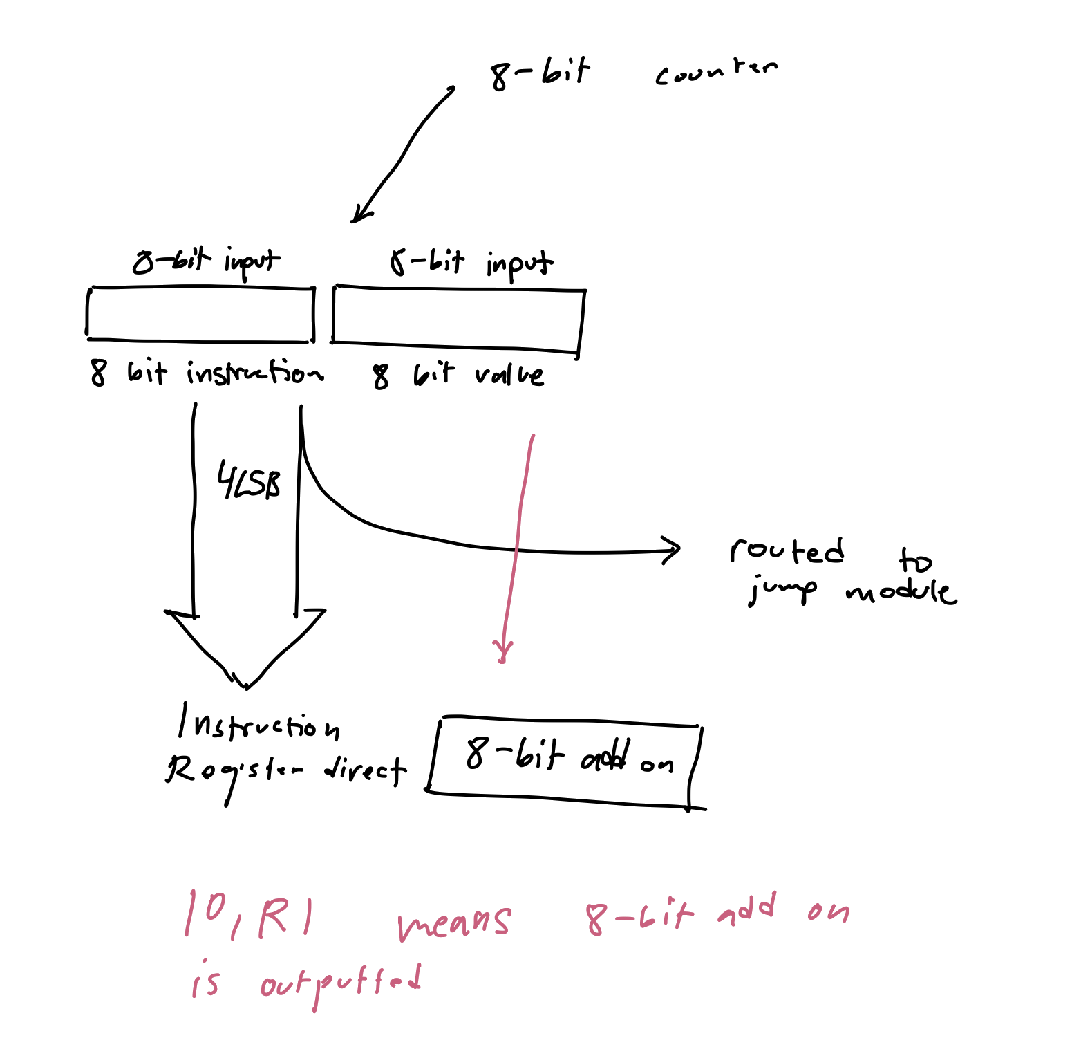
The ALU compares registers A and B, outputting a 2-bit code: 01 for A<B, 11 for A=B, 10 for A>B. Each 8-bit instruction encodes the condition in the instruction bits and the jump address in the data bits.
Example: a while loop
x = 0
while (x < 10):
    x += 1
print(x)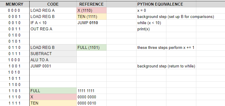
Since registers can't increment directly, we load 0xFF into register B and subtract — two's complement gives us an increment by 1. The program loops by jumping back to the comparison step until the condition fails.
3. Further development
There's a lot more that I've looked into and created for this computer. I was going through some old plans and found notes on how to implement a 256 byte RAM instead of the current 16 byte.
Some other changes I made which I want to note:
- 16x2 character LCD implementation
- Reducing instruction fetch cycle by 66% via a dedicated instruction bus
I hope you enjoyed reading, and learned something new about how computers really work. Perhaps the idea of what a "program" really is has changed, like it did for me. Pursuing this project made me more appreciative of how much our processors do that we don't get to see — for example, the implementation of recursion.
Best,
Ebrahim